In this project, we will go over how to connect an P-Channel MOSFET to a circuit for it to function as an electronic switch.
- How Does P Channel Mosfet Work
- P Channel Enhancement Type Mosfet Tool
- P Channel Power Mosfet
- P Type Mosfet Circuits
The type of P-Channel MOSFET we will use is the enhancement-type MOSFET, the most commonly used type of MOSFET.
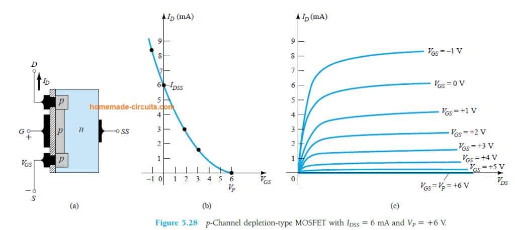
- In P-channel D-MOSFET, The source, drain, and channel is made up of P-type material upon an N-type substrate. P-channel has holes as the charge carrier. Therefore, to reduce the channel width or to attract electrons from the N-substrate, P-channel MOSFET is applied with positive gate voltage V GS.
- Enhancement-Type ('Normally OFF') P-Channel MOSFET is like an upside-down N-Channel MOSFET. It starts to conduct if Gate value is sufficiently lower than Source. If you connect the Source of a P-Channel MOSFET to VCC, then you can use a voltage between VCC (+) and Ground (-) to turn it ON and OFF.
Symbol depicts broken channel between 'S' to 'D' terminals. When positive voltage is applied to the gate, it will induce a channel by flowing minority carriers (i.e. Electrons) from P-type bulk into the concentrated layer. Figure-4 depicts drain characteristics and transfer.
MOSFETs, like BJTs, can function as electronic switches. Although unlike BJTs, MOSFETs are turned on, not by current, but by voltage.
MOSFETs are voltage-controlled devices. This means that a voltage applied to the gate controls whether the transistor switches on or off. When aP-channel (enhancement-type) MOSFET has no voltage at its gate, it is OFF and no current conducts across from source to drain; thus, the load connected to the MOSFET will not turn on.When there is sufficient voltage at the gate (about -3V), the MOSFET is on and current conducts across from the source to the drain to power on the load.
Know the distinction between a voltage-controlled device and a current-controlled device. MOSFETs are voltage-controlled. This means that only voltage hasto be applied to the gate for it turn on. It does not need current. Therefore, when we are wiring up the P-channel MOSFET, we simply connect the voltage source to the gate terminal. No resistor is necessary, as would be the case for a bipolar junction transistor, which is current-controlled. We simply connect a negative voltage to the gate terminal without an external resistor. Therefore, with a MOSFET, biasing the circuit is actually a little simpler than with BJTs.
Watch sky on your phone free. Components Needed
- IRF9640 MOSFET
- DC Motor or Buzzer
- 6 'AA' batteries or Dual DC Power Supply
In our circuit, we are going to use the IRF9640 P-channel MOSFET.
The IRF9640 is an enhancement-type MOSFET, meaning as more negative voltage is fed to the gate, the current from the drain to the source increases. This is in contrast to depletion-type MOSFETs, in which increasing negative voltage to the base blocks the flow of current from the drain to the source, while placing no voltage at the gate makes the MOSFET fully on.
Know that an P-channel MOSFET, like all MOSFETS, have 3 pins, the drain, the gate, and the source.

If you look at the back view of the transistor, as shown above, the leftmost pin will be the source, the middle pin is the drain, and the rightmost pin is the gate. This is a very different pinout than the N-Channel MOSFET, so make sure you observe this for your connection setup.
The gate terminal is where we connect about -3 volts to power on the transistor (to make it turn on).
The source terminal is where we connect our output device that we want to power. And when connecting our load, if the device is polarity-sensitive, such as LEDs and buzzers are, the anode terminal must be connected to the positive voltage, while the cathode end connects to the source terminal. Or else, it won't work, because current in an P-channel MOSFET flows from source to drain. If we hooked up an LED, reverse biased, so that its anode was connected to the drain terminal and its cathode was connected to the positive voltage source, it would not work.
The last terminal, the drain, simply connects to ground. Since current flows source to drain, the drain must be grounded to create a return path.
Ssh guide. The IRF9640 datasheet is can be be viewed here: IRF9640 MOSFET datasheet.
P-Channel MOSFET Circuit Schematic
The schematic for the P-Channel MOSFET circuit we will build is shown below.
So, this is the setup for pretty much any P-Channel MOSFET Circuit.
Negative voltage is fed into the gate terminal. For an IRF9640 MOSFET, -3V at the gate is more than sufficient to switch the MOSFET on so that it conductsacross from the source to the drain. Now that we have hooked up sufficient voltage to the gate to turn on the transistor, then we must supply voltage to our load on the source terminal of the transistor. Remember, one voltage is to turn on the transistor and the other voltage is to power the load once the transistor has been turned on.
The amount of voltage that needs to be connected to the load depends entirely on how much voltage the load needs to be powered on. If you are using a 6V DC motor or buzzer, then you connect 6V to the source terminal. If you are powering a 12V motor or buzzer, then you connect 12V.
Since the buzzer we are using in this circuit requires 6V, 6V is connected to the source terminal.
And this is how an P-Channel MOSFET is set up and works.
To see how this circuit works in real life, see the video below.
Related Resources
P Channel MOSFET Basics
How to Connect a Transistor as a Switch in a Circuit
How to Connect a (NPN) Transistor in a Circuit
Types of Transistors
Bipolar Junction Transistors (BJTs)
Junction Field Effect Transistors (JFETs)
Metal Oxide Semiconductor Field Effect Transistors (MOSFETs)
Unijunction Transistors (UJTs)
What is Transistor Biasing?
How to Test a Transistor
Transistors are the most popular semiconductors in the field of electronics. These are available in various types and configurations such as Bipolar-Junction Transistors (BJTs) and the Field-Effect Transistors (FETs) considered as the basic ones. These FETs are further classified as Junction field-effect transistors (JFET) and insulated gate field-effect transistors (IGFET). The transistor with input at the gate is insulated electrically from the main channel of current-carrying is referred to as IGFET or the metal oxide field-effect transistor (MOSFET). The electrode at the gate of these MOSFETs is made up of metal oxide. These MOSFETs operate in two modes and are classified as Enhancement MOSFET and Depletion MOSFET.
What is Enhancement MOSFET?
MOSFETs are usually classified into two types. They are Enhancement and the Depletion MOSFETs. The MOSFET that is basically in OFF condition which requires a certain amount of voltage at the terminal gate to turn ON is referred to as Enhancement MOSFET.
Web scraping beautiful soup tutorial. What is beautiful soup? Since 2004, Beautiful Soup has been rescuing programmers to collect data from web pages in a few lines of scripts. Beautiful soup is one of the most widely-used Python libraries for web scraping. As mentioned in their website, beautiful soup can parse anything we give it. Most commonly it is used to extract data from. Use requests and Beautiful Soup for scraping and parsing data from the Web Walk through a web scraping pipeline from start to finish Build a script that fetches job offers from the Web and displays relevant information in your console. Implementing steps to Scrape Google Search results using BeautifulSoup. We will be implementing BeautifulSoup to scrape Google Search results here. BeautifulSoup is a Python library that enables us to crawl through the website and scrape the XML and HTML documents, webpages, etc.
Due to the application of gate voltage the channel among the terminal of drain and source gets less resistive. If the applied voltage at the gate increases then the current flow from the terminals drain to the source increases until and unless it reaches its maximum point. The behavior of this type of MOSFET resembles the behavior of bipolar junction transistor (BJT).
The Schematic symbol of Enhancement MOSFETs of both p-channel and n-channel MOSFETs are:
Enhancement MOSFET Symbol
Construction
The steps involved in the construction of Enhancement MOSFET are:
How Does P Channel Mosfet Work
- Two N regions separated by a distance of 25 micrometers with heavy doping concentration are diffused on a lightly doped substrate of p-type. Those N-regions are enacted as the terminals drain and source.
- Over the surface, a thin layer of insulation called silicon dioxide is developed. The holes made on this layer establishes aluminum contacts for the terminal’s source and the drain.
- This layer of conduction acts as the terminal gate. It is laid over the silicon dioxide and on the entire area of the channel.
- But it doesn’t have any physical channel for conduction.
- The p-type substrate extended over the entire silicon dioxide layer in this type of enhancement MOSFET.
Enhancement MOSFET Diagram

Operation of an Enhancement MOSFET
The operation of the Enhancement MOSFET are
P Channel Enhancement Type Mosfet Tool
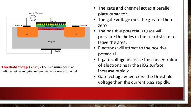
- To induce the channel positive polarity of the Gate to Source voltage is required. A large amount of voltage must be applied at the terminal gate for this operation.
- If the voltage applied at the terminals gate to the source is zero, Enhancement MOSFET doesn’t conduct. This can be the reason it is initially in the OFF condition.
- When the applied amount voltage at the terminal gate exceeds the limit of the threshold the current at the drain tends to flow through the circuit.
Let us consider a situation when the positive amount of the voltage applied at the Drain- Source by keeping the gate voltage as zero.
P Channel Power Mosfet
- In this situation, the p-type of the substrate and the two N-regions behave like the two junctions of PN.
- This makes both the junctions reverse bias and the leakage current tends to flow through the circuit.
- Now if the voltage applied at the gate is made positive. The minority carriers present in the substrate of p-type (that is electrons) get attracted to the positive potential of the terminal gate.
- These negative charge carriers get accommodated below the terminal of the gate. Further increment in the VGS will deposit more amount of carriers called electrons.
- The use of dielectric prevents the movement of these electrons across the layer of silicon dioxide.
- This accumulation results in the formation of the n-channel amid Drain-Source.
- This leads to the generated drain current flow through the channel.
- This drain current is proportional to the resistance of the channel which is further dependent upon the carriers attracted towards the positive terminal of the gate.
Hence from the above points, it can be concluded that the channel conduction is enhanced based on the positive potential of the gate terminal.
P Type Mosfet Circuits
Drain Characteristics of Enhancement MOSFET
The amount of current flow is dependent on the positive amount of the potential applied at the terminal gate. If the application of the potential is below the threshold then no current flow is evident through the terminal drain. If the voltage exceeds the threshold the device gets turned ON.
The Enhancement type MOSFET is well suited in the application areas where power devices are used. To increase the conductivity the amount of applied gate potential must also be increased. Because of the low resistance required to turn ON the device and high resistance offered while turning it OFF these devices are preferred for switching applications. After knowing the applications of Enhancement MOSFETs can you describe where the depletion-mode MOSFET is preferred?
